Air Valve Theory
For any nodal type in communication with atmosphere (e.g., Discharge to Atmosphere, Air Valve), air may be injected into the pipeline whenever the local (gauge) pressure drops to zero or below. In the specific case of an air valve, the injected air is expelled from the pipeline under pressure through a restrictive orifice in order to cushion the subsequent impact of the rejoining adjacent liquid columns. Thus, in the following discussion, although we will refer to an air valve, it should be observed that the injected air will remain at atmospheric pressure for all other nodal types capable of allowing the entry of air. Consequently, in the current version of HAMMER, air entering or escaping at a small crack or hole in the piping, valve and/or joints could only be represented by an air valve.
There are two air pocket models embedded in HAMMER: Elastic (Concentrated) and Rigid Column (Extended). The former is a more standard treatment wherein each air pocket is localized at its formation point, whereas the latter is an innovative rigid column representation of the adjacent branches with tracking of the air-liquid interface.
Modes of Operation
For Air Valves in HAMMER, there may be up to three orifice diameters: one for inlet and two for outlet; demarcated by either a Transition Volume or a Transition Pressure. The diameters of three orifices and the transition volume/pressure are input parameters (some of which are only available for certain Air Valve Types - see Air Valves for details) which materially affect the performance of the Air Valve.
It should be noted that the Transition Volume is an artificial construct that approximates the inner workings of combination (a.k.a. triple-acting, or three-stage) air valve. The volume adopted is usually the volume of the body of the air valve, since floats typically operate inside the air valve to reduce the air outflow orifice size once liquid starts to enter the air valve body (i.e. when the volume of air remaining is less than the volume of the body of the valve). The Transition Pressure is simply an internal pressure in the pipeline, above which the large diameter air outflow orifice is forced closed. The user must select whether a valve utilizes a Transition Volume or Transition Pressure as the trigger to switch between the large diameter orifice and the small diameter orifice.
For any of the three orifices, HAMMER automatically calculates air flow throttling due to the "sonic velocity" using a formulation after Comolet (1961). Using this formulation the air mass flow rate, QM is determined as follows:
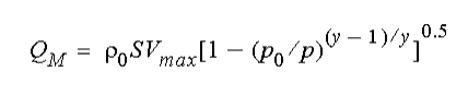 (1)
(1)  is the density of air at 4°C and 1 atmosphere (=1.293 g/l), S=0.6A, with A being the cross-sectional area of the orifice.
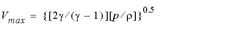
 is the exponent in the gas law, p is the absolute pressure, the subscript 0 denotes standard conditions, and
  = constant. For air inflow, (1) is again applicable, except that the ratio within the square brackets is inverted to be p/p0 as p0 >p in this instance. The exponent, , in the gas law is hard-coded as 1.4, which corresponds to adiabatic compression/expansion appropriate for the typically rapid processes which occur.
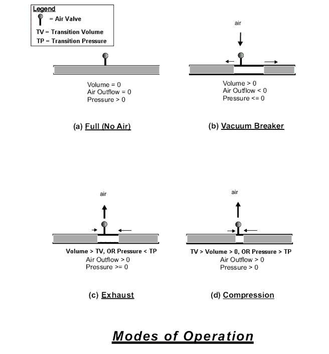
With reference to the Modes of Operation figure below, four modes of air valve operation have been identified: (a) full (no air), (b) vacuum breaker, (c) exhaust, and (d) compression. Under normal steady-state conditions, the pipeline will be full (of liquid) as the (gauge) pressure exceeds zero. Should the pressure decline to zero, the Air Valve will serve as a vacuum breaker as it opens to allow the entry of air. During this phase, an expanding air pocket forms, but eventually system conditions can cause the flow to reverse. If the air volume is greater than the Transition Volume (or the internal pressure is less than the Transition Pressure), air is released through a large-diameter orifice in exhaust mode; when the remaining air volume decreases below the Transition Volume (or the internal pressure increases above the Transition Pressure), the large-diameter orifice closes and the small-diameter orifice opens to vent the remaining air, which now undergoes significant compression.
Full and Partially Full Branches
An air valve may be connected to more than one pipe branch and at any instant it is quite possible for some branches to be full while others have air volumes. Consequently, ambiguity arises when flow towards the air valve occurs in a full branch. To process this scenario, the following rules are adopted within the software: